Skip to content

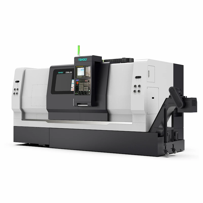
A slant bed CNC lathe is a type of CNC lathe whose bed is angled relative to the horizontal plane. Its design aims to improve machining rigidity, chip removal efficiency, and machining accuracy, especially excelling in high-efficiency batch processing.

Contents
1. Basic Concepts
2. Core Advantages
3. Main Structure and Key Components
4. Core Machining Capabilities
Common Machinable Geometric Types
Common Angle Classifications and Their Impact on Machining Paths
5. Application Scenarios
6. Selection Considerations
1. Basic Concepts
The bed of a slant bed CNC lathe is designed at an angle. The spindle box and feed system are usually located on the same sidewall. This results in a lower center of gravity, easier distribution of turning forces, and better rigidity and stability at high speeds. This structure makes it easier for chips to escape from the turning area, offering advantages in machining accuracy and surface quality, especially when machining complex contours such as shafts, cylinders, threads, and worm gears. The following points can help you quickly understand and distinguish this type of machine tool.
Key Working Principles:
• Workpiece Fixing and Rotation: The workpiece is clamped in a chuck or fixture, fixed to the spindle, and rotates with it, providing machining stability.
• Tool Movement: The tool is mounted on a tool post, and the CNC system controls its movement along the X and Z axes. The slant bed design helps disperse turning forces, reducing tool wear and deformation.
• Linear Guides: High-precision linear guides provide accurate linear motion with low friction and minimal error, thereby improving machining accuracy and surface quality.
• Turning Process: The tool and workpiece are shaped under the combined action of rotation and feed. The slant bed helps reduce the impact of turning forces on the CNC machine tool, improving machining results.
• Automatic Control: The CNC system controls parameters such as feed, depth of cut, and turning speed through programming, ensuring machining accuracy and efficiency.
2. Core Advantages
• Improved Rigidity and Stability: The slant bed effectively disperses turning forces through its tilt angle, maintaining high rigidity and stability even under heavy turning loads, reducing vibration and deformation, thereby improving machining consistency and reliability.
• Improved Machining Accuracy
The linear guideway system reduces friction and motion errors, significantly improving positional accuracy and surface finish, especially advantageous in high-precision applications.
• Enhanced Chip Removal and Cooling Management
The slant bed design facilitates natural chip and coolant removal, reducing chip buildup interference with the tool and workpiece, improving machining stability and efficiency, and lowering secondary cleaning costs.
• Increased turning Efficiency
The machine tool can withstand higher turning forces, suitable for high-speed and heavy-duty turning modes, increasing output per unit time and meeting the needs of applications with high efficiency and productivity requirements.
• Space Saving and Adaptability
Compared to some traditional horizontal bed machine tools, the slant bed structure is generally more compact and occupies less space, making it suitable for workshops with limited space while still providing high machining capacity.
3. Main Structure and Key Components
Bed and Guideways: Provide overall rigidity and positioning accuracy of the machine tool. The slant bed design helps reduce thermal deformation accumulation. Common implementations include combinations of slant bed slides and guideways, facilitating chip removal and thermal management.
Spindle: Responsible for workpiece rotation and turning force transmission, typically including the spindle box, drive system, lubrication and cooling system, while also ensuring thermal stability and rotational accuracy.

Tool Post and Feed Mechanism: The arrangement of the tool post and guideways forms the core of the machining path. Slant beds commonly use angled or rear-mounted tool posts to improve rigidity and achievable machining speeds, while also facilitating chip removal.
Tailstock and Slide: Used for workpiece positioning and support, ensuring the static and dynamic stability of long workpieces. The rigidity and alignment accuracy of the tailstock directly affect the coaxiality of end face and hole machining.
Toolpath and Chip Removal System: Slant bed designs are usually paired with convenient chip removal schemes to avoid chip accumulation in the guideway area, improving machining continuity.
Electrical and Control System: The CNC unit, servo drive, sensors, and protection devices are responsible for machining program execution, servo feedback, and status monitoring, and are key components for achieving high precision and stability.
4. Core Machining Capabilities
Common Machinable Geometric Types
• Machining of straight cylinders, slant cylinders, arc surfaces, conical surfaces, and other curved surfaces;
• Machining capabilities for complex contours such as threads, grooves, and worm gears;
• Composite processes supported by multi-station turrets or power turrets, enhancing the machining content within a single clamping cycle. (Overview description from industry structure and application introductions.)
Common Angle Classifications and Their Impact on Machining Paths
Common angles include 30°, 45°, and 60°. The larger the angle, the more significant the impact of the bed on chip removal, thermal management, and guideway stress, thus altering the toolpath projection, tool change point, and feed strategy. 45°/60° is commonly used, achieving a good balance between machining rigidity, chip removal efficiency, and CNC machine tool compactness. Specific path optimization requires consideration of workpiece geometry, length, tolerance requirements, and chip removal/cooling layout.
5. Application Scenarios
Aerospace: For applications requiring high surface quality, strict dimensional tolerances, and stable, repetitive machining, slant bed CNC lathes are ideal. Their thermal stability and high rigidity help ensure stable machining of critical components such as end faces, outer diameters, and threads.
Common machined parts: Small aerospace structural components, engine end covers, bearing housings, seal rings, etc.
Automotive Manufacturing: For high-volume, batch machining scenarios with precise part-size tolerance requirements, slant bed lathes are suitable because their chip removal and toolpath optimization significantly improve consistency and tool change efficiency in mass production.
Common machined parts: Valve positioning sleeves, drive shaft ends, gear shaft end faces, bearing housings, etc.
Engineering Machinery: For applications requiring high rigidity and thermal deformation control, slant bed lathes can stably machine complex contours such as inner and outer diameters, chamfers, stepped surfaces, and end faces.
Common machined parts: Valve body cavities, valve cores, flanges, etc.
Medical Devices: For applications requiring extremely high surface roughness and coaxiality, the stability of slant bed lathes helps achieve micron-level precision in repetitive machining.
Commonly machined parts: Miniature shafts, support components, positioning bushings, precision threaded parts, etc.
General-purpose parts: With the cooperation of multi-station turrets and efficient chip removal systems, slant bed lathes can achieve high output and consistency, suitable for mass production of high-precision parts.
Commonly machined parts: Small mechanical parts, shafts, cylindrical and conical surface assemblies, threaded parts, etc.
6. Selection Points
① Define Machining Objectives
Confirm workpiece material, diameter, length, batch size, precision and surface roughness targets, and whether multi-process linkage is required.
② Preliminary Specification Setting
Determine the bed type, working stroke, spindle power/speed range, guideway type, and fixture scheme based on the workpiece range.
③ Performance and Stability Evaluation
Evaluate bed rigidity, guideway rigidity, thermal stability, vibration control, and stability under high loads. Perform finite element analysis or on-site comparative testing if necessary.
④ Cost and Maintainability Analysis
Compare the total cost, maintenance difficulty, spare parts availability, and training requirements of different models.
⑤ Trial Run and Verification
If conditions permit, arrange a trial run or comparative verification with similar processes to confirm machining accuracy, surface quality, and production cycle time.
⑥ Decision Making and Implementation
Based on the comprehensive evaluation results, determine the final model and configuration, and develop an installation, commissioning, and training plan.
Tenoly boasts a rich series of CNC machine tools and can quickly match and recommend the most suitable model based on your workpiece material, size, output, and accuracy requirements, saving you time and effort. We also have a global sample center that can provide sample making and batch trial production services. Contact us for your customized solutions!
FAQ
Is a slant bed always better than a flat bed?
Not necessarily. Slant beds offer advantages over flat beds in terms of rigidity, chip removal efficiency, vibration control, and space utilization, especially suitable for medium to large parts and scenarios requiring high turning forces.
What slant bed angle is most suitable?
There is no universally accepted optimal angle. It depends on a comprehensive evaluation of the machining process, workpiece geometry, tool configuration, spindle rigidity, guideway stability, and forming and chip removal requirements.